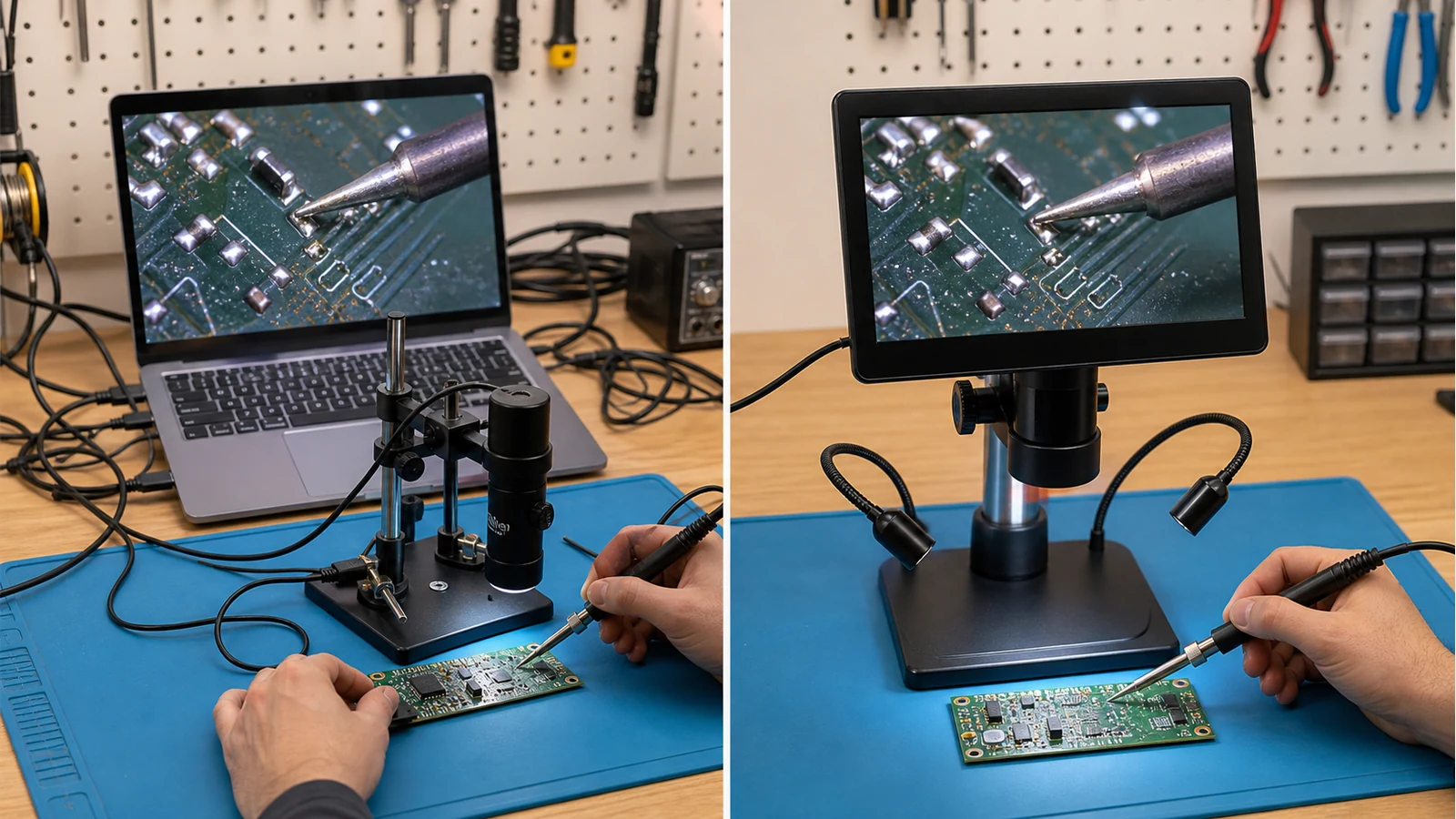
Hdmi Vs Usb Microscope Latency Soldering Uk
Direct answer: if you are soldering live under the microscope, choose the display path for hand-eye timing first. A standalone HDMI or built-in screen workflow is usually the safer fit for active SMD work; a USB-to-PC workflow can still be excellent for still capture, measurement software or documentation, but the computer path may add enough delay to feel wrong at the iron tip.
Why latency matters at the solder joint
Latency is not just a specification number. On a dense phone board or laptop board it becomes the gap between where your hand is and where the screen says your hand was. Public camera-interface guidance commonly frames HDMI microscope output as closer to real time than USB capture through a computer; MCscope USB vs HDMI camera guide describes USB delay as PC-dependent and HDMI as the lower-latency path. Treat those figures as interface guidance, not a measured promise for every product.
For UK repair benches, the painful moments are bridge correction, dragged pins, hot-air nudging and 0201 placement. When the picture arrives late, you tend to overcorrect. That is why screen size, resolution and advertised 4K are secondary to whether the live view feels synchronous enough for the task.
Decision Table
| Bench task | Better default | Reason |
|---|---|---|
| Live SMD soldering and hot-air rework | HDMI or built-in screen | Prioritises hand-eye sync while tools are moving. |
| Static inspection and report images | USB can work well | Capture software, storage and annotation may matter more than instant response. |
| Teaching or shared bench review | HDMI screen plus optional capture | Everyone sees the same view while the operator stays upright. |
| Measurement-heavy lab work | USB with validated software | Workflow depends on software and calibration rather than just display delay. |
Do not buy latency marketing blind
Do a simple shop-floor check before committing: move fine tweezers under the lens, tap a pad, and watch whether the tip and screen feel coupled. Then repeat with the PC capture route if you need it. A buyer guide for soldering microscopes also warns against chasing maximum magnification ahead of working distance and usable live view; see Tomlov soldering microscope guide.
When USB is still the right answer
USB is not bad technology. It is often the sensible route for still images, batch documentation, microscope software and archiving. If you mainly inspect finished joints, photograph damage for customers, or need software tools on Windows or macOS, a USB workflow may be the practical centre of the bench.
Where a 10.1-inch HDMI system fits
If your priority is live repair, a 10.1-inch screen system with HDMI-style real-time viewing and a soldering lens is relevant after you have confirmed your work is live-rework-heavy. The next step is conditional: compare your tasks against the product route at InchHDMI Pro 10-inch digital microscope, especially if you need both screen viewing and occasional PC output.
For a related hardware trade-off, read digital vs stereo microscope for SMD soldering and microscope working distance for hot-air rework.